Frequently Asked Question
Technical Information OBDI ECU Anatomy
Introduction
The Honda ECU, like your Honda engine, is a very well designed piece of equipment made to work in many cars under many varying conditions of temperature and altitude. This tech article looks at the functions of the ECU and how it differs from some of the piggyback and standalone systems available.
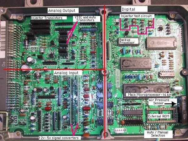
Backup Microprocessor
The backup microprocessor monitors the function of the main microprocessor, ROM and sensors. In the event of a serious failure it takes over the running of the computer in what is called limp home mode. In this mode the ECU needs only two sensors to run. TDC (top dead centre from the distributor) and TPS (throttle position). In fact you can remove entirely the ROM and primary microprocessor and your Honda will still run. Limp home mode is rev limited to 3500 RPM with a fixed ignition and rather rich fuel setting with the engine check light permanently on.
This is military specification redundancy designed to keep you going even in the event of multiple sensor failures. No other vehicle maker we are aware of uses a backup processor and this level of redundancy.
Analog Input
This is where the 12V signals are conditioned and converted into 5V for processing - such as the distributor signals TPS and MAP.
Analog Output: Injector driver transistors
These are excellent quality transistors, which make a substantial contribution to how the well the Honda ECU drives injectors. These transistors do not even get warm (except when low impedance resistors are incorrectly wired in without the Honda resistor box!). All Honda ECUs drive high impedance injectors or low impedance injectors with an external resistor box.
Hondas switch the injectors on and off rapidly (red line). With poorer quality transistors the injectors do not open or close as quickly, resulting in less fuel delivered in the same amount of time. The difference is most noticeable at small injector durations - part throttle.
Increase your fuel pressure and the extra fuel line pressure can slow the injector opening. Another reason to keep low fuel pressures.
Larger injectors with a heavier pintle also take longer to open and close due to inertia and show a similar effect.
We have found Honda ECUs work particularly well with larger injectors. For example one Hondata customer using 830 cc injectors in a B20 turbo has drivability indistinguishable from stock and achieves 30mpg.
Barometric Air Pressure sensor
This sensor tells the ECU at what altitude you are running. The ECU uses this information to make small fuelling adjustments at altitude. This is one of the reasons for Honda excellent idle and part throttle characteristics in all conditions.
Interpolation
Interpolation is the process the computer goes through to calculate the fuel and ignition values between the marked points on the fuel and ignition map. For example, what fuel value should be used at 800 RPM at 400 mb of air pressure? The mathematics are the same for the Honda or any standalone, but there can be differences on how the ECU turns that number into an injector opening time.
The Honda (red line) times the injector opening and closing time to an accuracy of about a millionth of a second, which on a 1ms pulse width is an accuracy of 0.1 % e.g., 96.1, 96.2 ...165.9, 166. Many standalone systems (black line in the diagram above) step the injectors as little as 8 or 16 times - 96, 100, 104 ... 162, 166. This step is probably the result of digital to analog conversion.
There are two schools of thought on this.
- The first is that the differences between the two are too small to be significant.
- The second is that Honda must do this for a reason.
Fuel injection specialists support the second school of thought saying that Honda's precise injector control contributes to drivability compared to some standalone systems with a stepped output for injector duration.
Fuel and ignition maps
VTEC Honda ECUS have two complete and independent fuel and ignition maps for each camshaft. We are not aware of any standalone that has this capability.
Having 2 maps makes the tuning process very straight forward.
- Set the VTEC point to 7000 RPM and tune the low speed cam fuelling and ignition
- Set the VTEC point to 3000 RPM and tune the high speed cam camshaft.
- Plot the torque curves and set the VTEC point to the crossover RPM
This method ensures a very smooth VTEC transition (some JR customers have complained their VTEC was not working when it in fact was)
Be aware that stock Honda ECUs have 10 VTEC points, not one, and at light throttle the VTEC point can be 1000-1500 RPM higher than at full throttle. If you are running with a standalone with one ignition and fuel map and have a variable VTEC point (or a piggyback with a fixed VTEC point), then you cannot have the correct fuelling and timing for both cams all the time.
Variable load and RPM scaling.
Honda scale their RPM points closer together where needed for fine tuning (see the red lines and arrows below). For example at idle and VTEC crossover the RPM points are 200-250 RPM apart. At high RPM the tuning points can be as far apart as 500 RPM. The same goes for load, although it is not as easy to see on these graphs.
What the graphs from this 95 GSR mean:
- The low speed and high speed fuel and ignition curves are vastly different.
- The shape of the fuel curves are very closely related to torque.
- After peak torque, less fuel is needed as can be seen below in the low speed cam fuel curve after 6000 RPM.
 |  |
 |  |
VTEC controllers
The ECU switches maps when the high speed VTEC cam is engaged. When an external VTEC controller is added, the cam is switched with the ECU running on the incorrect map for that cam. Depending on the RPM you can be as much as 10% fuel and 6 degrees ignition timing out. A typical VTEC controller will adjust 8 RPM positions by 2 load positions for a total of 16 tuning points. Compare that to 20 RPM positions by 10 load positions for each cam for a total of 400 tuning points. (* this is for a stock ECU. Hondata adds 240 tuning points for boost)
So in summary, external VTEC controllers upset the stock fuelling and ignition by switching the cam, have no ignition correction and very coarse fueling correction compared to the stock ECU.
Short and long term fuel trim.
OBD I and OBD II both have a function called fuel trim. If, at part throttle the ECU sees the air fuel ratio is too rich or lean, the ECU makes immediate (short term) corrections. Over time those corrections are learned and transferred to a long term trim value that is applied all the time. Unplugging the ECU is one only way of erasing the long term value. So depending on how you alter the fuel with an external piggyback type controller, the ECU can learn and override it.